Creating Generative Design
First things first.
Before starting this section you should:
- Learn about NodeBox concepts.
- Learn about random: to learn how randomness works in NodeBox.
- Learn about subnetworks.
Generative Tower.
Nodebox is ideal for creating generative design. We've covered a few of them before (f.e the arab tiling principle).
Suppose we want to make a network that stacks building blocks (represented as simple rectangles with a difference in width and height) on top of each other. I want to be able to tell each tower how many segments it contains and i want to be able to reset the width and height of each segment.
Let start with building the segment.
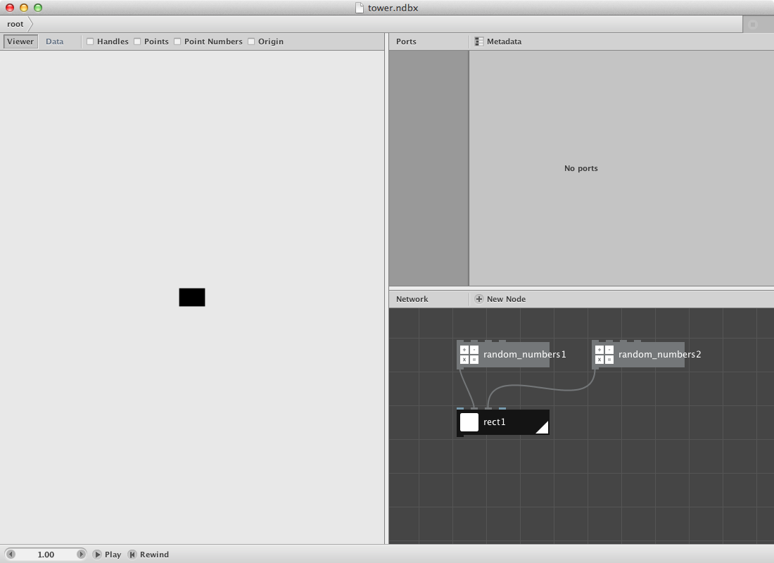
- Create a rect node. Keep it at its default setting.
Since I want the ability to change width and height parameters of this rectangle I will create a random number and use its' seeding principle to change its' value.
- Create two random number nodes. Set Seed of the first one to 0 and to 1 for the second one. Pointing to the same seed would result in a square but I want rectangles with a different width and height.
- Set Start to 1 and End to 50 of random_numbers1.
- Set Start to 20 and End to 50 of random_numbers2.
- Connect random_numbers1 to Width port of rect1.
- Connect random_numbers1 to Height port of rect1.
Now for the stack:
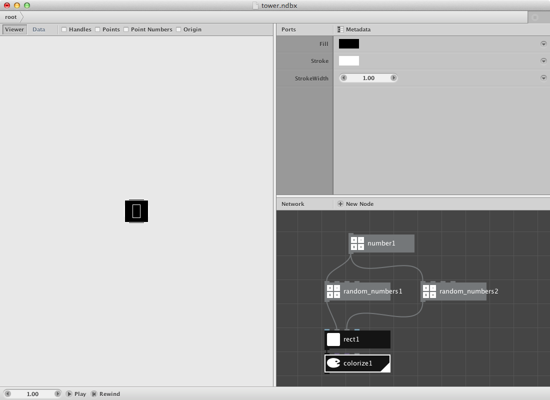
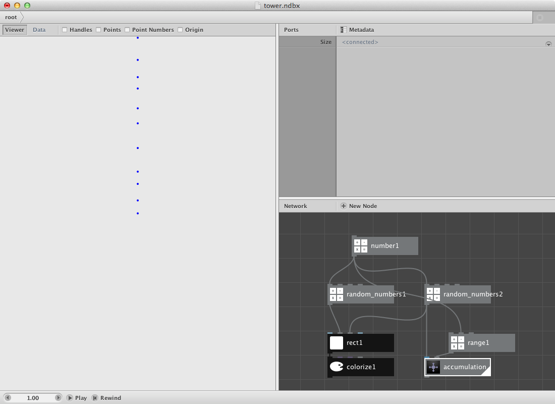
- Create a number node and set Value to 10.0.
- Connect it to Amount of random_numbers1 and of random_numbers2.
- Create a colorize node and connect rect1 to it. Change the strokecolor to white and enter 1.0 as the Strokewidth.
The result is ten rectangles all on top of each other. We will have to create a procedure to stack them on each other with reference to their height value.
- Create a slice node and set Start-index to 0.0 and Size to 1.0.
- Connect random_numbers2 to it.
- Create a sum node and connect slice1 to it.
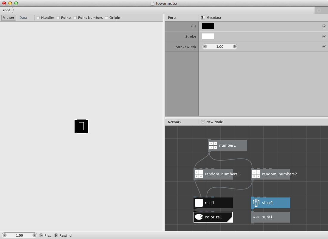
The idea is to make a sommation netwerk that returns the sum value for 0, 0-1, 0-2, 0-3, 0-4 and so on. We can do this by changing the Size value of slice1. Try it out and notice that the sum is higher with a higher size. We will do this as many times as there are numbers in random_numbers2. Let's create a subnetwork to store this function and enable to send a range of numbers to it.
- Select slice1 and sum1 by dragging over them.
- Right-click one of them and choose “group into network”.
- You can now give the network a new name. Name it "accumulation".
Let's get back to the child nodes to implement a few modifications. I want to be able to send a number to the Size of slice1 so I need to publish this specific parameter. In addition I want to create a point based on this number.
The idea is that the value can be used to push the y coordinate of each rectangle up based on the combined height of his predecessors. This means we have to negate the number and send it to a make point node.
- Right-click the accumulation node and select 'Edit Children'.
- Right-click on Size port of slice1, choose "Publish" and call it 'size'.
- Create a negate node and send sum1 to it.
- Create a make point node and send negate to Y port. Leave X at 0.0.
- Render the make_point1 node and go back to the root network.
Back in the root you should be able to see a modification in the accumulation node. It has an extra port that refers to the Size of the internal slice node (the port is a gray one meaning it expects a value).
Now let's give it a value.
- Create a range node and connect number1 to its' End port.
- This will result in a list of numbers starting from 0 and ending at the amount of number1.
- Connect range1 to Size port of the accumulation node.
The next step is to use the points for the location of the rect.
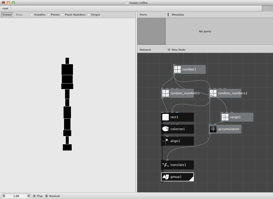
- First create an align node and set Valign to Bottom. I want all rectangles to start on top of the origin point and then translate them. Connect colorize1 to align1.
- Create a translate node. Connect align1 to it's Shape port and the accumulation node to its' Translate port.
- Create a group node to merge all paths into one geometry object. Send translate1 to it.
- Render group1.
You can change the tower by:
- Changing Value of number1 which will add segments to the tower.
- Changing Seed of random_numbers1 which will change the width of each segment.
- Changing Seed of random_numbers2 which will change the height of each segment and calculate a new set of points based on these new values.
- Try it out first.
We will create a subnetwork from this procedure and publish some variables that will enable us to change the look of the tower.
- Select all by dragging over them.
- Right-click one of them and choose “group into network”. Name the network "tower".
- Right-click tower node and select 'Edit Children'.
- Right-click on Value port of number1, choose "Publish" and call it 'number-of-segments'.
- Right-click on Seed port of random numbers1, choose "Publish" and call it 'change-widths'.
- Right-click on Seed port of random numbers2, choose "Publish" and call it 'change-heights'.
- Click on the root tab in the adress bar or right-click somewhere on the network view to choose "Go Up".
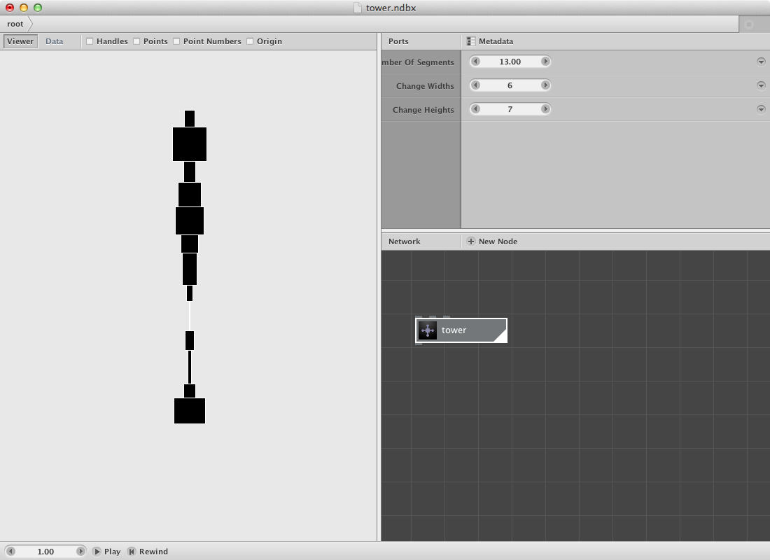
The tower node has three ports:
- Change Number Of Segments to 13.0.
- Change Change Widths to 6.
- Change Change Height to 7.
The new tower looks like this:
Read the subnetworks page and try creating a number of towers or a skyline:
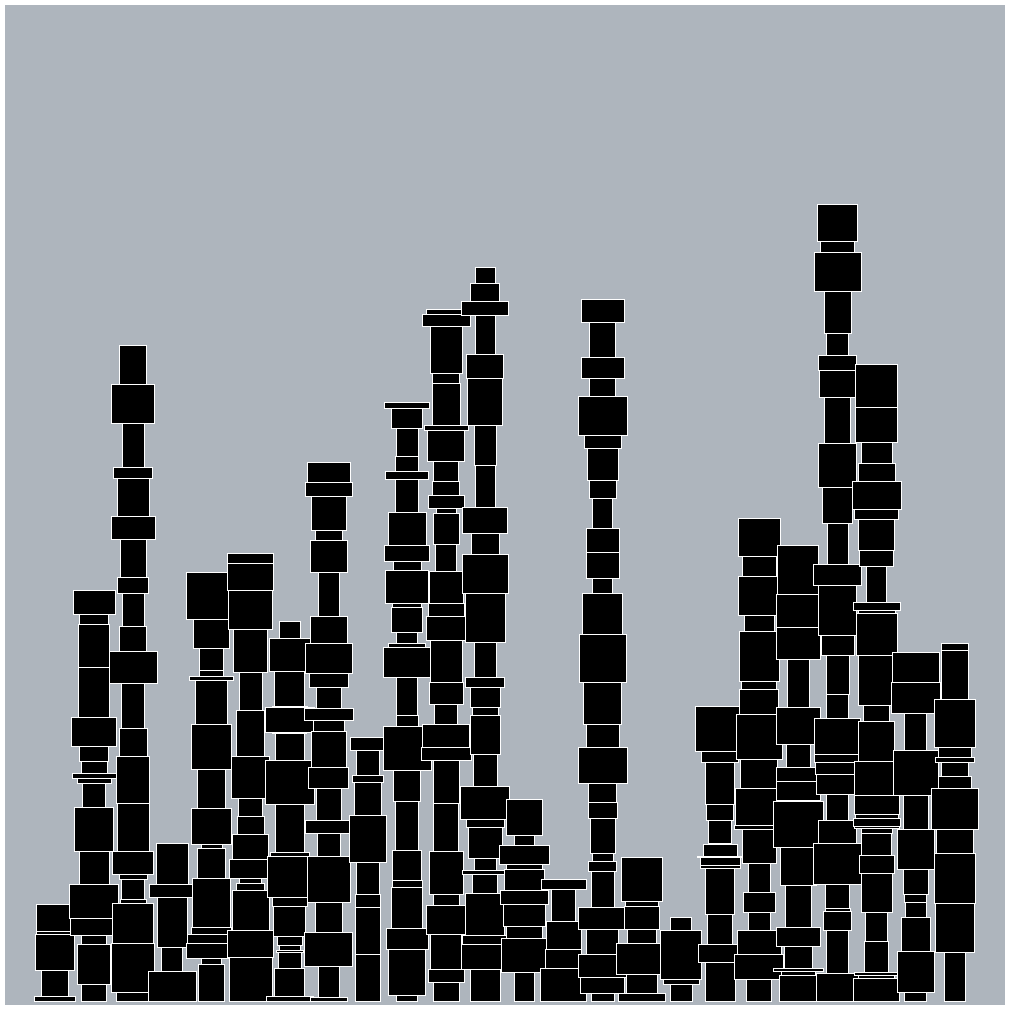
Changing the basic segment will change the complete building / city:
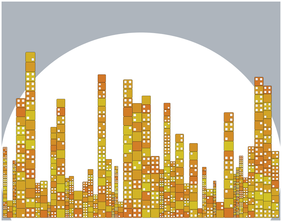
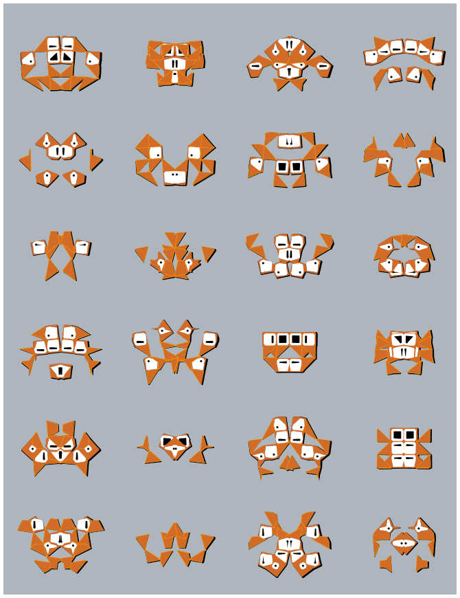
Styled Invader.
Suppose i want to recreate something like the invader example as decribed on the subnetworks page. In stead of using simple rectangles i will create a few shapes to work with.
- Create a rect node and set Width to 100.0 and Height to 100.0. Additionally set Roudness to 20.0 and 20.0.
- Create an other rect node and set Width to 100.0 and Height to 150.0. Change the position on the x-axis to 50.0.
- Create a rotate node and set the angle to -45.0. Connect rect2 node with this angle node.
- Create a compound node and send rect1 to the shape1 port, send rotate1 to the shape2 port. Set function to Difference.
Output should be the half of the original rectangle (rect1 node):
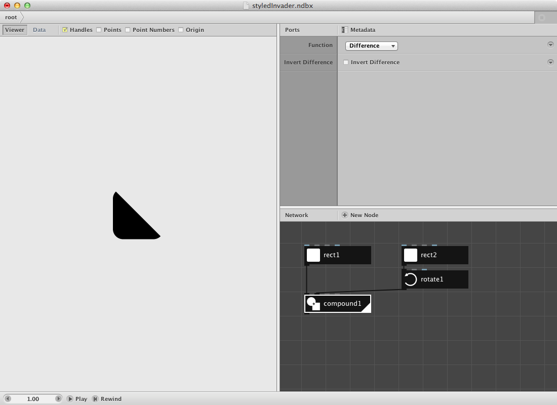
I want to be able to use this shape with a difference in rotation. Therefore:
- Create a rotate node. Connect compound1 to it.
- Create a range node. Set Start to 0.0, End to 360.0 and step to 90.0. Rendering this node will result in a list of numbers: 0,90,180,270.
- Connect range1 to the angle port of the rotate node. This will result in 4 paths (have a look at the data view to proof this right) all on top of each other but with a variety in rotation. The first one rotates 0 degrees, the second one 90 and so on.
- Create a colorize node and give a Fill color and a Stroke color. Make shure to set the Strokewidth which is 0.0 by default. Set it to 1.0. The last step will enable you to see the layers better in the viewer pane.
Now let's create something that may represent an eye.
- Create an ellipse node. Set Width to 80.0 and Height to 80.0.
- Create a compound node. Connect rect1 to Shape1 and ellipse1 to Shape2. Set the function to Difference.
- Create a colorize node. Connect compound2 to it's Shape port.
- I will use ellipse1 for the pupil as well. Create a scale node and set Scale to 20.0 and 20.0.
- Create a combine node and send colorize2 to it's first port, scale1 to it's second one.
- The output of combine1 consists of two paths. Create a group node and send combine1 to it to create a geometry object.
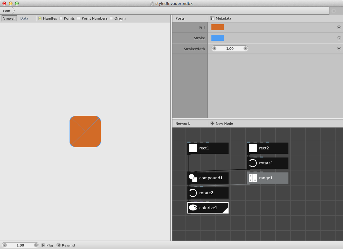
In a later stage i want to be able to select one of these shapes. Next few nodes make this happen:
- Create a combine node and connect colorize1 to it's first port. Connect group1 to it's second one.
- Create a slice node and connect combine2 to it. Set Size to 1. Change the Start_index to obtain a different path. From 0 to 3 will select the triangle shapes with their difference in rotation. 4 will return the 'eye' shape.
Our network is getting a bit big so let's create a subnetwork.
- Select all nodes by dragging over them.
- Right-click one of them and choose “group into network”.
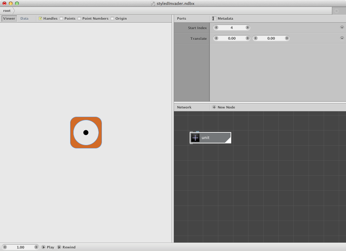
- This will leave you with one node, subnet1. Right-click it again a rename "unit".
Let's get back to the childnodes to implement a few modifications. I want to be able to send a number to the Start_index of slice1 so i need to publish this specific parameter. I also want to be able to give a unit a location so i will have to implement and publish a translate node:
- Right-click on Start_index port (in the networkview) of slice1 and choose "Publish" and give it an appropriate name.
- Create a translate node. Connect slice1 to it's Shape port.
- Right-click on Translate port of this new translate node and select "Publish". Select it as rendered node.
- Click on the root tab in the adress bar or right-click somewhere on the network view to choose "Go Up".
Back in the root you should be able to see a modification in the unit node. It has two port: a first one referring to the Start_index (a gray one meaning it expects a value) and a second one to Translate (a blue one meaning it expects a point).
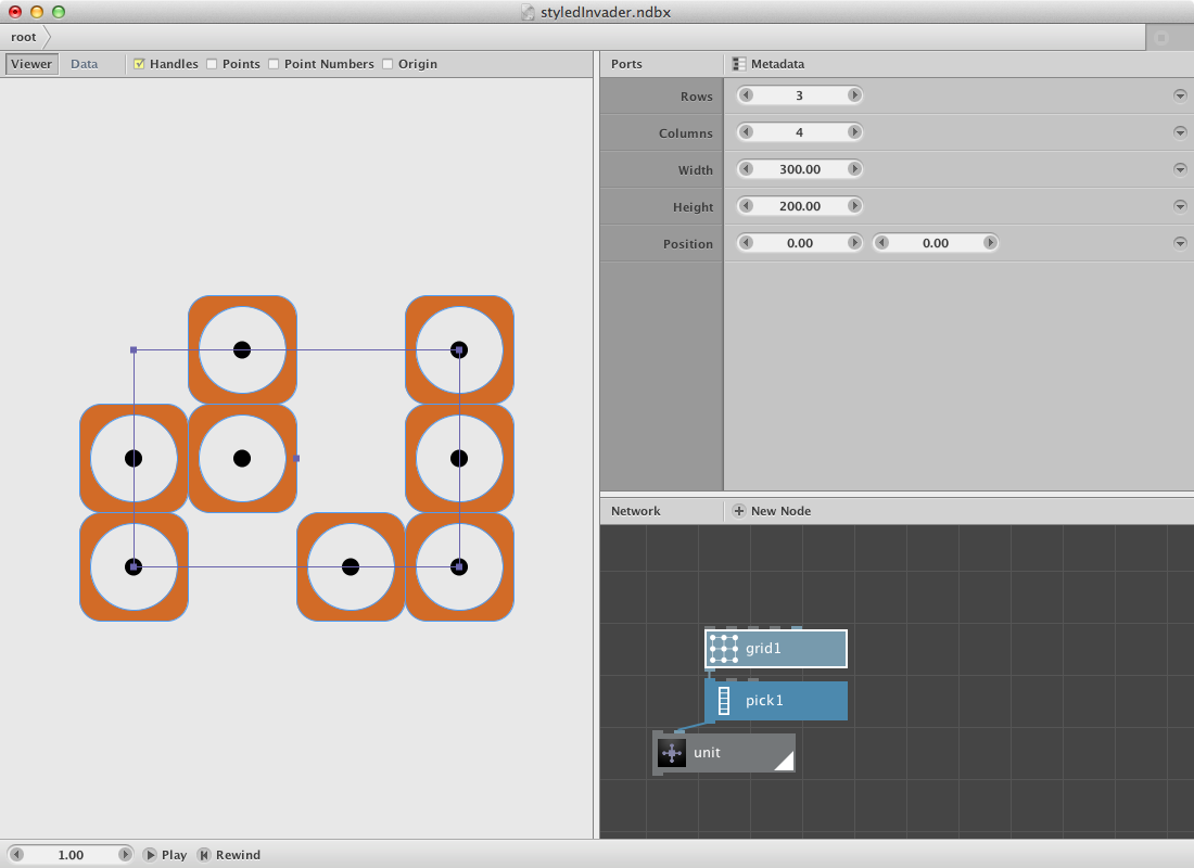
This new unit node will be placed on certain locations of a grid.
- Create a grid node and set Rows to 3, Columns to 4, Width to 200.0 and Height to 300.0.
- Creat a pick node. Connect grid1 to it and set Amount to 8.
Let's introduce a procedure that does not always pick the same unit but picks a random one instead. First we need to know how many times a unit has to be created. We can count the amount of pick1.
- Create a count node and connect pick1 to it.
Based on this count we can create an amount of random numbers varying between 0 and 4 (remember that on 0 till 3 were the triangle shapes and on 4 was the eye)
- Create a random numbers node and connect count1 to Amount port. This will result in a number of random floating numbers.
- To convert it to integers (we can not select piece 3.41) create a to integer node. Connect random numbers1 to it. This should result in a list of absolute numbers between 0 and 4.
- Connect to integer1 to Start_index port.
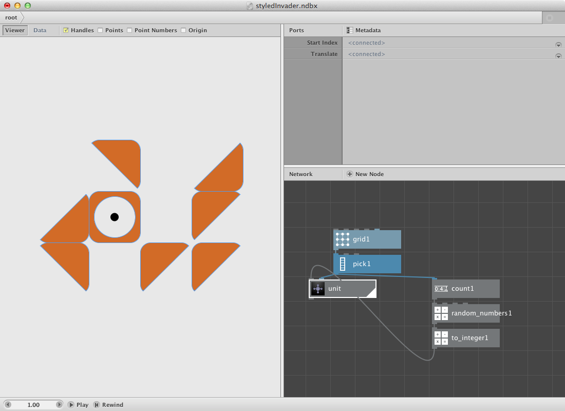
Change the Seed of pick1 to create another result.
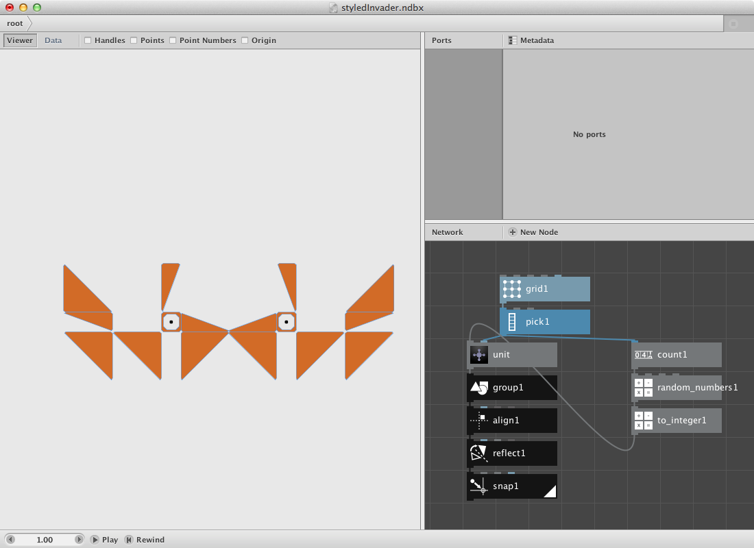
This is half of the result. Next step is to align it to the right side of the origin. In order to do this an important step has to be made: render the unit node and have a look at the Data tab in the viewer pane. Notice that there are 8 paths in the list: 1 for each unit. If we would align this as is it would result in a similar aligment for all units. To avoid the translate information we will have to group these 8 paths into a single geometry path.
After the alignment we will reflect it to obtain an invader. Last step is an implementation of a snap node which will change the shapes over a snapping procedure.
- Create a group node and connect the unit node to it.
- Create an align node and set Halign to Left. Connect group1 to it: the shape should shift to the right side of the origin.
- Create a (black) reflect node and set Angle to 90.0. Connect shape1 to it.
- Create a snap node and set Distance to 150.0 and Strength to 50.
- Render snap1 node and change Seed of pick1.
Let's create a few of them.
- Select all the nodes and right-click to 'Group into network'. Rename it to invader.
- Right click it again and 'Edit Children'.
- Publish Seed of pick1 and name it seeda.
- Publish Seed of random numbers1 and name it seedb.
- Go back to the root network: the invader has two ports now.
- Create a grid node and set Rows to 5, Columns to 1, Width to 700.0 and Height to 1700.0.
- Create a count node and connect grid1 to it.
- Create a range node. Connect count1 to its End port.
- Connect range1 to Seeda and Seedb.
- Create a translate node. Connect invader to Shape and grid1 to Translate. Render it.
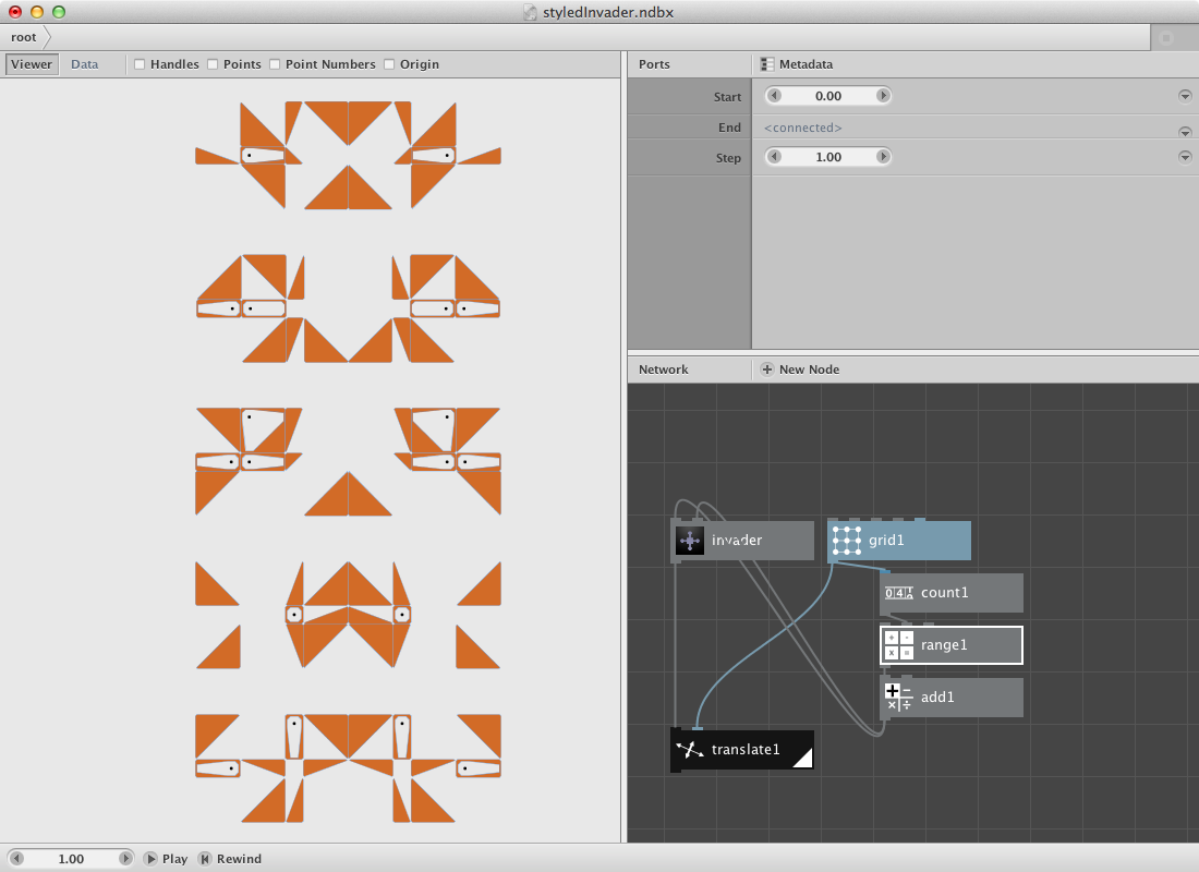
Below is the same procedure with a few modifications. A shadow was added and the 'invadergrid' was altered by rows, columns and dimension.